


Technical Guidelines
Our chemical etching guidelines have been created to guide you through designing for the photochemical etching process.
Contact UsDesigning for chemical etching
Below is an overview of the technical considerations for designing precision metal components for chemical etching. For a more detailed understanding, download our technical guideline document below.
Download technical guidelinesSuitable materials, thicknesses & sheet sizes
We stock over 2,000 material types in a wide range of sheets sizes, thicknesses and grades. We also supply specialist materials on request.
| METAL TYPE | THICKNESS RANGE | MAXIMUM SHEET SIZE |
|---|---|---|
| Steel and stainless steels | 0.01mm – 2.5mm | 600mm x 1500mm |
| Nickel and nickel alloys | 0.01mm – 1.5mm | 600mm x 1500mm |
| Copper and copper alloys | 0.01mm – 1.5mm | 600mm x 1500mm |
| Aluminium | 0.01mm – 1.5mm | 600mm x 1500mm |
Standard etching tolerances
| MATERIAL THICKNESS | MINIMUM TOLERANCE | TECHNICAL TOLERANCE | MINIMUM HOLE/SLOT | MINIMUM LAND AREA |
|---|---|---|---|---|
| 0.01mm – 0.1mm | ±0.025mm | Contact us | 0.1mm | 0.050mm |
| 0.1mm – 0.25mm | ±0.025mm | Contact us | 100% metal thickness | 75% metal thickness |
| 0.25mm – 2.5mm | ±10% metal thickness | Contact us | 100% metal thickness | 75% metal thickness |
Corner radii
With photo etching, the smallest inside and outside corner radius achievable is directly proportional to the thickness of the selected metal being processed.
A - Outside corner radius – minimum of 75% material thickness
B - Inside corner radius – minimum of 100% material thickness

Hole & Profile Geometries
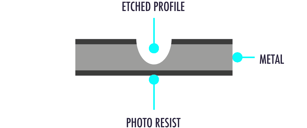
During etching, the etchant attacks the material laterally and vertically resulting in an edge “cusp” which is typically 10 to 20% of material thickness.
Precision Micro can control the etch cusp, allowing for a range of profiles. This gives products unique characteristics, such as sharp cutting edges or conical openings.
1 Single-sided etch
Used to achieve a specific depth, profile or for thin gauge metals
2 Convex profile
Industry standard edge condition for through-etched components
3 Parallel profile
Used to reduce etch cusp
4 70/30 etch
Combines through etching and depth etching and can also be used to produce conical apertures or cutting edges
5 Double-sided depth etch
Used for surface engraving on both sides
6 Concave etch
Used to achieve a straighter edge profile
7 2/3 stage etch
Used to achieve multiple depths, requiring additional imaging
Component tags
Tags are small threads of metal used in the etching process to secure components within the sheet. They become essential when precise etch tolerances are needed or when components need subsequent electroplating or assembly.
Precision Micro provides various etch tags to choose from, depending on the components shape, thickness or intended use.
Following manufacturing, components can either be delivered with tags intact within the sheet or as separate individual parts. Depending on the required size, design or tolerance specifications, we can also produce components without etch tags.
1 Protruding tag

The default tag which does not affect the surface area of the part
2 Half-etch protruding tag

This aids component removal from the sheet
3 Recess tag

This is used when a tag protrusion is not permitted
4 Half-etch recess tag

This removes tag protrusion and aids component removal from the sheet